Building a monster subwoofer
It's not often that I find much to laugh about in a hi-fi shop, but recently I had an experience which had the staff wondering whether to laugh along with me, or just to call the men in white coats. I wanted to buy a subwoofer, that is, a very-low frequency, high-output loudspeaker for handling deep bass and low-pitch sound effects. So I went along to my local hi-fi dealership (yes, there are a few still left), and had a conversation that went something like this:
Me: I'm interested in buying a subwoofer.
Salesman (indicating a small ugly box with fins on): Well, this one's very popular, one of our biggest sellers.
Me: Yes? How much?
Salesman: 699 pounds.
Me: (laughing) really? 700 quid? No!
Salesman: It's got excellent low-frequency performance. Really shakes the house.
Me: Get away! Show me something sensible.
Salesman (huffily, indicating smaller, uglier box with fins): Well, if you're on a tight budget this one's not too bad for 300 pounds.
Me (starting to find it difficult to keep a straight face): what's its power handling?
Salesman: 75 Watts.
Me: 75 watts continuous, right?
Salesman: for 200 pounds? Don't make me laugh, Sir. 75 watts peak!
At this point I collapsed in a hysterical laughing fit, and only just made it to the door before the staff called the hospital.
When I recovered my wits, I found I had come to two conclusions. First, I couldn't afford a subwoofer, even though I really wanted one. Second, even if I could afford one, they were invariably ugly boxes with fins. I didn't want something that looks like it came from a nuclear reactor in my living room.
So I began to wonder if I couldn't make something half decent myself. Ordinarily I wouldn't attempt to build a loudspeaker: it's notoriously difficult to work out the optimal dimensions of the cabinet, and the necessary woodworking skills are beyond me. However, a subwoofer is somewhat different.
First, there will typically be only one driver unit in the cabinet, so the design does not have to be a compromise between the needs of the multiple drivers. Second, the subwoofer will be driven by its own amplifier and cross-over unit. This means the electronics can compensate, to a degree, for imperfections in the design, and we don't have to implement a passive crossover (great big coils and what-nots).
Happily, there's lots of subwoofer information on the web. Most of what I needed to know came from Brian Steele's DIY audio web site. This site contains common-sense advice and detailed mathematics; with this information, a few hours, and a spreadsheet program, it's relatively easy to come up with an enclosure design that will give an acceptable frequency response for a given driver unit.
Brian Steele's DIY subwoofer site
Design notes
What do I want from a subwoofer?
- The entire job should cost less than £100, ideally much less.
- It should be able to handle at least 100 Watts. That's continuous Watts, not imaginary `music power' Watts.
- It should produce significant output below 40Hz, and useable about below 30Hz. A 3dB cut-off point of about 40Hz should be about right. In other words: really, really loud, really, really low.
- It should require no elaborate carpentry techniques or tools to build, and the design should be tolerant of less-than-optimal construction. This suggests a sealed-enclosed design, rather than something that requires tuning.
- It should look nice and match my furniture; small size was not a priority, but an enclosure of more than about three cubic feet would probably not be well tolerated.
- It should offer low distortion and a reasonable transient response; however, my listening environment is far from ideal, and it did not seem sensible to have this as top priority.
Driver
With a total budget of £100, it was clear that specialist `hi-fi' units would be out of reach. The requirement for serious volume at less than 40Hz suggested that I needed a 12-inch driver. Commercial manufacturers can, to a degree, get good low-frequency performance from smaller drivers by careful signal conditioning in the built-in amplifier; this option is not really available to a DIYer. Even popular custom subwoofer drivers like NHT's 1259 would eat up the whole budget. This essentially limited me to a car audio unit. These are much cheaper than hi-fi devices, but offer good low-frequency performance and high power handling. After an evening of web searching, I selected the Jensen `Explorer' 12-inch model. This unit has a resonant frequency of 30Hz, and advertises a power handling of 400W (which I assume corresponds to about 100W in real terms). For those who are interested, the relevant Thiele-Small parameters are as follows.
fs 	30Hz
Qts 	0.7
Vas 	160 l
SPL 	92 dB/W/m
Cabinet size
Traditionally, sealed enclosure designs tend to be large. The transient response improves with a larger cabinet size, as does the flatness of the frequency response, although there is a limit beyond which little improvement is gained.
The parameter of interest here is the Qtc figure for the driver/enclosure combination. Hi-fi designers like to get this to around 0.7, and certainly less than 1.0. With the Jensen driver, calculations indicate that a figure of 0.7 is unobtainable, with any enclosure. Even to get a Qtc of 1.0 requires an enclosure of nearly 6 cubic feet. Now, although I am not that bothered about size, 6 cubic feet is the capacity of a typical refrigerator.
In fact, it appears that the Qtc and the cut-off frequency improve most dramatically with an increase in enclosure size from 1 cubic foot to 2 cubic feet; there is a smaller improvement from 2 to 3 cubic feet, and progressively smaller improvements after that. So in the end I settled on about 2 cubic feet as offering the best compromise. This leads to a predicted Qtc of about 1.3 and a 3dB cut-off point at 41 Hz. It also predicts a resonant peak at about 60Hz and, with a large Q, this is likely to be pronounced (see predicted frequency response below).
However, there's a limit to what can be achieved with a 30-quid driver, and my listening room is likely to introduce larger discrepancies in frequency responce than this. Increasing the enclosure to 3 cubic feet would appear to offer only a modest improvement in the frequency response.
Cabinet design
I wanted a cabinet that had a furniture-like appearance (rather than a science-fiction appearance), and yet would be easy to construct. In addition, I wanted to be able to mount the amplifier in a compartment in the cabinet, so it would be invisible in normal operation, but accessible for adjustment and connection. I decided to make the cabinet slightly taller than required to match the 2-cubic-foot design capacity, and have the top three inches or so as a concealed compartment, as shown below.
The amplifier and electronics sit in the compartment at the top of the enclosure. I adjusted the size of the compartment during assembly, to account for the size of the amplifier I intended to use. Ventilation holes prevent overheating in normal operation, while the whole top panel can be removed for high-power operation,
or for maintenance.
Construction
For maximum stiffness, and because it looks nice, I constructed the cabinet from solid pine stripboard of 18mm thickness. Because my carpentry is not up to much, I designed the enclosure so that it could be assembled entirely from lengths of 400mm-wide board; the only sawing necessary was to cut this board into lengths of the right size, as shown in the figure below. The height of the cabinet depends on the space required to accommodate the amplifier: 600mm in my case, allowing an 80mm compartment.
The cabinet is supported internally using lengths of 34mmx34mm timber at all joints. The supports are held against the panels with steel L-brackets, fixed by screws and copious amounts of strong wood glue. All the panels are glued except the back, which needs to be removable for maintenance. This is screwed into place from the outside; all the other panels are screwed from the inside so that the screws are not visible. A gasket of rubber strip sits between the rear panel and the rest of the cabinet; this improves airtightness and reduces the tendency of the rear panel to vibrate under high output. The final structure is very stiff and extremely heavy. If I had the tools, and the skill, I would have rounded the edges of the cabinet, or joined the panels using something more elegant than butt joints. However, with a few thick coats of varnish it doesn't look too bad.
A large (280mm dia.) cut-out is required for the Jensen driver, and a smaller one between the driver enclosure and the amplifier compartment for the connection panel. This panel is a steel dish about 60mm square, onto which I mounted two 4mm banana posts for the connection to the driver. The driver was screwed to the enclosure from behind; it includes a sealing ring to make it airtight with this sort of mounting. The insides of the cabinet are lined with acoustic cladding. After soldering the connection posts to the driver terminal, and stuffing with acoustic foam, the rear panel can be screwed on and the job is finished.
How did it end up?
The total cost of the job worked out to be £83, not including sundries like screws and sandpaper.
At the moment I am driving the subwoofer from a Kenwood amplifier that isn't doing anything else (pending construction of a dedicated amplifier). The Kenwood is supplied from the subwoofer output of a Yamaha DSP system, which crosses over digitally at about 90 Hz, so no separate crossover (I assume) is required.
Given the low cost and the home-made construction, the subwoofer doesn't sound at all bad. The low-frequency effects on Dolby Digital 5.1 soundtracks are awesome, and bass-heavy music sounds pretty good. The resonant peak is not especially obvious in music, probably because it is masked by other resonances in the room.
The limiting factor in the sound output level is the construction of my house. At high output the floor, doors and windows vibrate; but the volume is physically painful by this point, so it is unlikely to be a problem in practice. Also, I have neighbours.
The next job will be to build a dedicated amplifier and power supply to fit in the amplifier compartment.
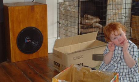
The photo below shows what the subwoofer looks like in place.
Published 2026-02-24, updated 2026-02-24
Categories
audioConverted from my Gemini capsule.